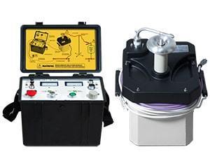
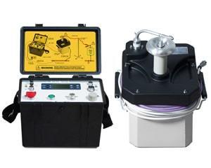
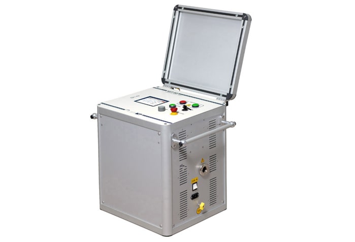
VLF-60
PORTABLE HIGH-VOLTAGE VLF TESTER
Portable tester VLF-60 is used for:
- VLF (0.1 Hz) withstand testing of cables with polymeric (PE, XLPE, TRXLPE, EPR, etc.) insulation;
- Hipot testing of various solid dielectrics (generators, transformers, switchgear, etc.) with DC+ and DC- voltage;
- Cable faults conditioning by initial insulation burning;
- Vacuum circuit breakers testing;
- Cable sheath testing and fault pinpointing.
VERSATILITY

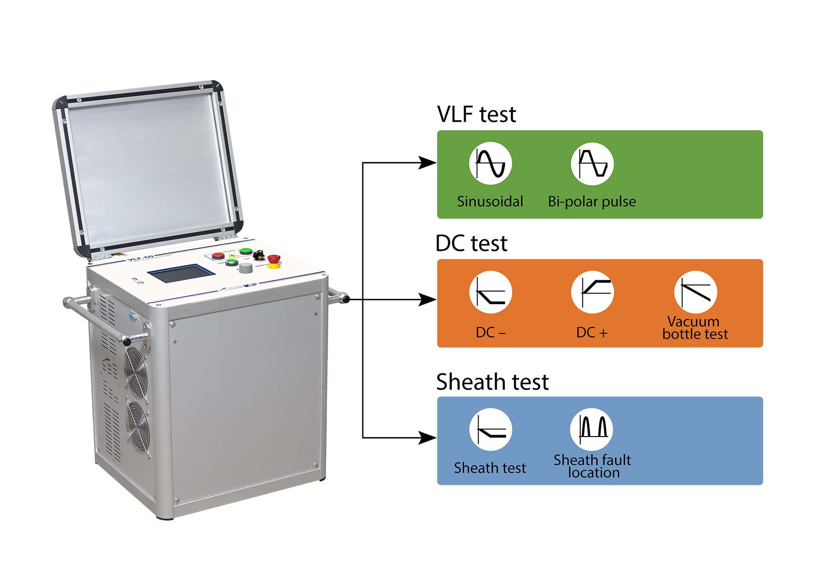
Apart from very low frequency (VLF) and DC withstand testing, VLF-60 system also performs cable fault conditioning by initial burning faulty insulation, tests cable sheath and pinpoints its faults.
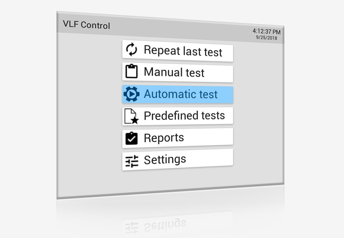
MANUAL AND AUTOMATIC OPERATING MODES
The system allows to carry out tests in both automatic and manual control modes.
In the manual mode the operator enters all test parameters, which makes VLF‑60 suitable for testing a wide range of electrical equipment according to various standards and regulations.
In the automatic mode minimal test settings entries are required: the operator only selects a test object type and voltage rating and the system automatically sets all the necessary test parameters according to IEEE 400.2-2013.
TESTING HIGH-CAPACITANCE OBJECTS
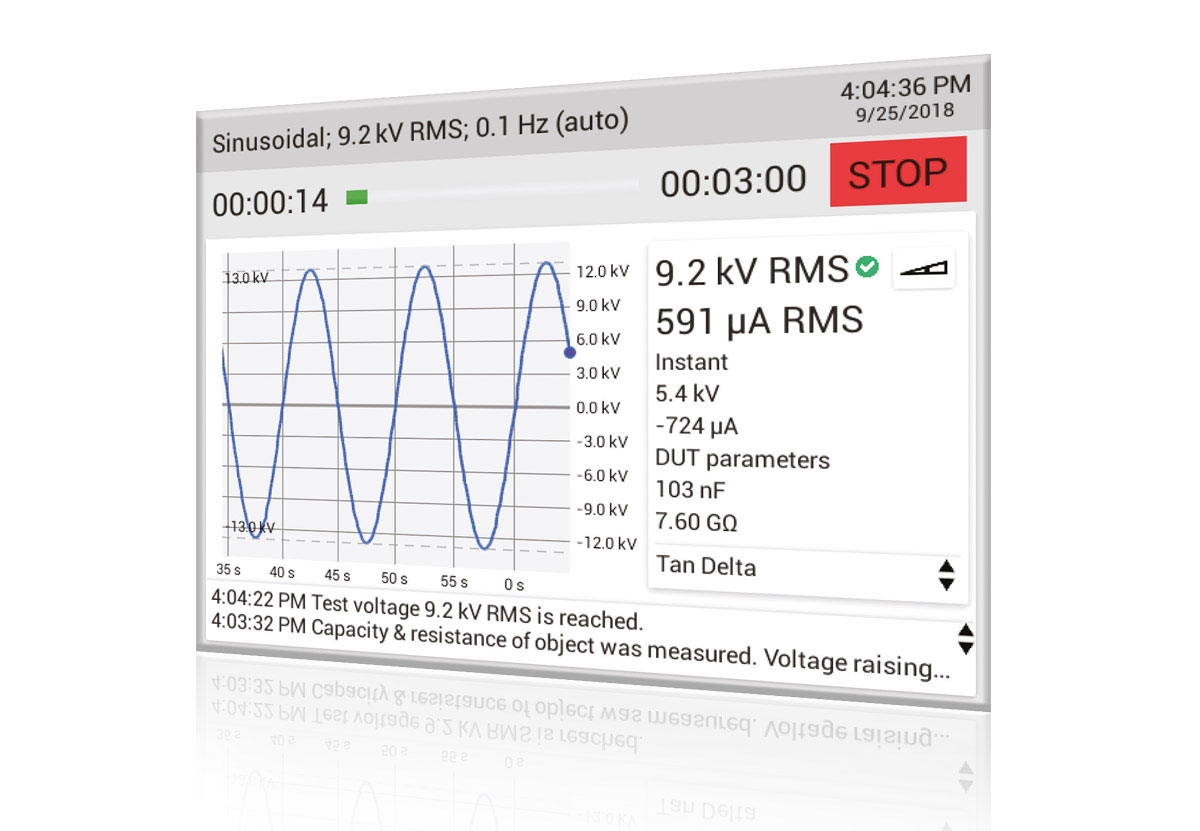
At the start of every test, VLF-60 measures the resistance and capacitance of an object under test. Based on the obtained results, the system evaluates its power output capability. If the system is not able to output the voltage of a required magnitude and frequency for a given load, it will automatically reduce the output frequency. Thanks to such output frequency optimisations, the VLF-60 can be used effectively for testing objects with capacitance up to 10 µF.
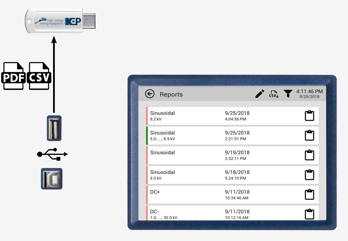
10,000 TEST REPORTS STORAGE
Non-volatile memory of the system capable of storing up to 10,000 test reports.
It is possible to search and view test reports right from the display of the system.
Test reports may be exported from the system to a USB memory stick in CSV or PDF format without using a PC.
TOUCH CONTROL
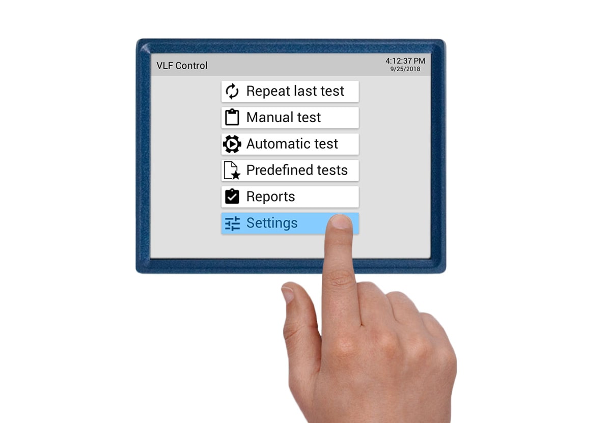
The main user interface component is a touch-sensitive colour TFT display, which is used for navigating menus and entering data. During a test, an output voltage wave is visualised on the display in real time.
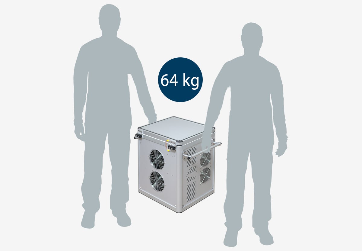
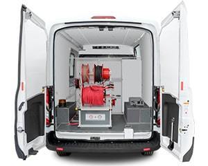
PORTABILITY AND SMALL WEIGHT
VLF-60 system is fitted with carrying handles and weighs only 64 kg, which enables operational comfort both in the lab and in the field conditions.
SAFETY
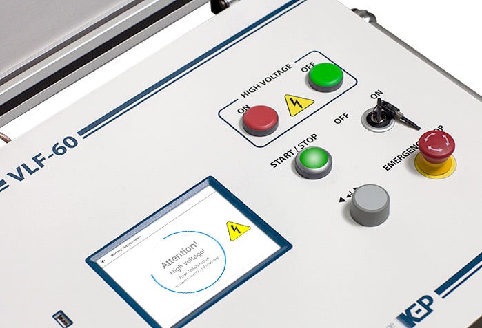
✓ Dual discharge device (internal automatic protection).
✓ Visual indication of high voltage presence on an object under active test.
✓ Visual indication of residual or stray voltage presence on an object after conclusion of a test.
✓ Sound alarm when high voltage is switched on.
✓ Emergency stop button.
✓ Operator keylock switch.
✓ Protective earthing.


| Output voltage | Adjustment and indication ranges: | ||
| ■ Sinewave | 0.1 … 62 kVPEAK (44 kVRMS) | ||
| ■ Bi-polar pulse | 0.1 … 62 kVPEAK | ||
| ■ DC+ | + | (0.1 … 60) kV | |
| ■ DC- | minus | (0.1 … 60) kV | |
| ■ Vacuum bottle test | minus | (0.1 … 60) kV | |
| ■ Sheath test | minus | (0.1 … 10) kV | |
| ■ Sheath fault location | + | (0.1 … 10) kV | |
| Setting and indication resolution | 0.1 kV | ||
| Relative indication accuracy | ± [2 % + 2 dgt*] | ||
| Indication | Real time voltage wave visualisation | ||
| Output current | Indication ranges: | ||
| ■ Sinewave | 0.1 … 40 mAPEAK (26 mARMS) | ||
| ■ Bi-polar pulse | 0.1 … 40 mAPEAK | ||
| ■ DC+ | + | (0.1 … 40) mA | |
| ■ DC- | minus | (0.1 … 40) mA | |
| ■ Vacuum bottle test | minus | (1 … 1000) μA | |
| ■ Sheath test | minus | (0.1 … 40) mA | |
| ■ Sheath fault location | + | (0.1 … 40) mA | |
| Indication resolution | 1 μA; 0.1 mA | ||
| Relative indication accuracy | ± [2 % + 2 dgt*] | ||
| Output frequency (sinewave, bi-polar pulse) | Output frequency setting range | 0.01 … 0.1 Hz, resolution 0.01 Hz | |
| Frequency selection |
■ Automatic ■ Manual |
||
| Output power | up to 1200 W | ||
| Breakdown management | Burn on arc (keep arc burning) | Insulation is burnt in the pace of a fault for the duration set in the range of 1 … 5 minutes | |
| Trip out on arc (current limit trip) | If a flashover is detected, the test is stopped | ||
| Metering |
■ Voltage and current (RMS and/or PEAK) ■ Object under test capacitance ■ Object under test resistance ■ Test time |
||
| Object under test | Load capacitance range ** | 0.1 nF … 12 μF | |
| Load resistance range ** | 10 kΩ … 20 GΩ | ||
| Maximum load |
■ 1.0 μF at 0.1 Hz, 44 kVRMS ■ 5.0 μF at 0.02 Hz, 44 kVRMS ■ 10.0 μF at 0.01 Hz, 44 kVRMS |
||
| Duty cycle | Continuous, unlimited | ||
| Controls and interfaces | Display | 5.7” colour TFT, 640 × 480 px, capacitive multi-touch | |
| Menu languages |
■ English ■ Russian ■ Chinese (simpl.) ■ Others (option) |
||
| Secondary control interface | Rotary encoder with “ENTER” button | ||
| Connection interfaces |
■ USB-A (user memory stick, FAT32) ■ USB-B (service only) ■ RS-485 (service only) |
||
| Internal memory | 10,000 test reports | ||
| Safety | Grounding |
■ Protective earthing ■ Automatic internal dual discharge |
|
| Protection | ■ Thermal circuit breaker | ||
| High voltage presence signalling | ■ Indication of high voltage presence on the object under test | ||
| High voltage switch off |
■ EMERGENCY STOP button ■ Power keylock switch |
||
| Ingress protection rating (according to EN 60529) | IP 21 (with lid closed) | ||
| Power supply and consumption | Mains supply voltage | 110 … 230 VAC, ±10% | |
| Mains supply frequency | 50 / 60 Hz | ||
| Power consumption | up to 1.5 kV•А | ||
| Physical | Dimensions, H × W × D | 528 × 577 × 408 mm | |
| Weight | 64 kg | ||
* dgt – least significant digit.
** Values measured on the high AC voltage may significantly differ from the values measured by a standard low-voltage multimeter.