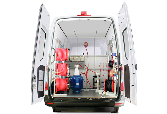
ETL-35K
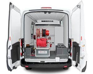
CABLE AND SUBSTATION EQUIPMENT TEST VAN
ETL-35K is a versatile multipurpose cable and substation test van with three-phase connection to electrical objects.
ETL-35K system has a multitude of applications in electrical equipment testing and maintenance: testing cable insulation with DC voltage up to 60 kV, detecting very small leakage currents during surge arrestors testing, high-voltage testing with AC voltage up to 100 kV at industrial frequency, tracing underground utilities, pre-locating and pinpointing cable faults, and measuring the capacitance and tangent delta of various electrical objects at industrial frequency.
ETL-35K is fitted with a collection of traditional and modern safety systems which ensure the comprehensive operator protection.
THREE-PHASE CONNECTION

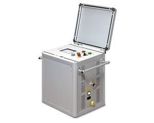
ETL-35K allows to connect to up to three coble cores simultaneously with an option to select the desired core to be tested from the control panel.
Three-phase connection makes fault location quick, easy and safe – it enables phase comparative pre-location methods, yet does not require an operator to switch the connection cables.

DC & AC TESTING
Van-based cable fault and test system ETL-35K allows to carry out withstand insulation testing with high DC voltage up to 60 kV and high AC voltage up to 100 kV at industrial frequency (f = 50 Hz).
MEASURING LEAKAGE CURRENT OF SURGE ARRESTERS

A microammeter included with the system allows testing surge arresters with DC (rectified) voltage up to 60 kV and measuring the leakage current with up to 0.01 mA significance.
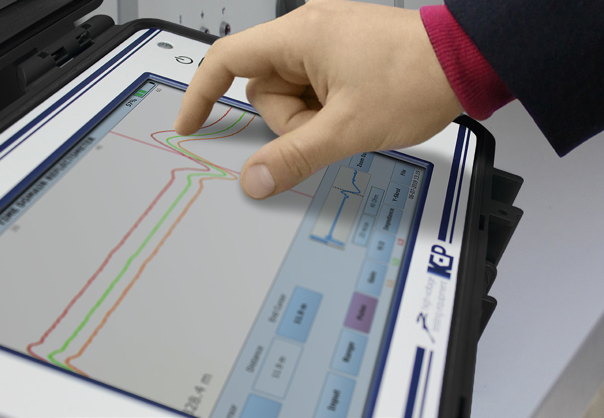
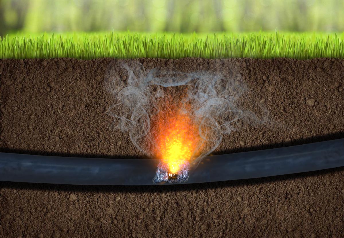
FAULT PRE-LOCATION
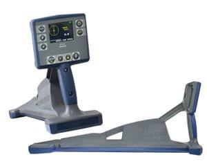
Detachable time-domain reflectometer RIF-9, supplied with the ETL-35K, is used for detecting and determining the distance to various types of faults in electrical power cables with the main pre‑location methods:
Low-voltage method
- TDR (time-domain reflectometry): low-resistance faults and breaks.
High-voltage methods
- ARC/ARC multi-shot (single impulse / multiple impulse arc reflection method): high-resistance and unstable faults.
- ICE (impulse current envelope method): high-resistance faults that cannot be converted to low-resistance ones by burning faulty insulation.
- DECAY (voltage wave oscillation method): faults with high breakdown voltage.
FAULT BURNING
ETL-35K is equipped with a powerful burn unit with output current up to 6 A in voltage ranges (0 … 1 kV / 5 kV / 10 kV / 20 kV), and 12 A current in the voltage range of (0 … 0.5 kV).
Burning allows to convert high-resistance faults into low-resistance ones, which makes it possible to subsequently apply pre-location and/or pinpointing methods for precise fault localisation.

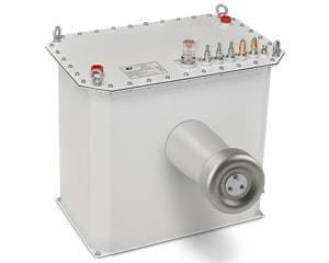
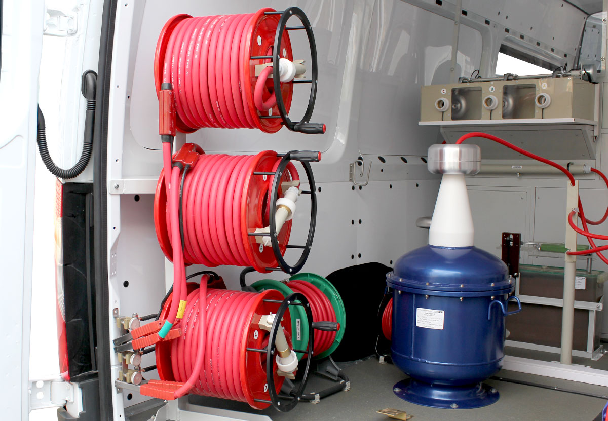
SURGE WAVE GENERATOR WITH VOLTAGE LEVELS SWITCH
A surge wave generator with up to 2000 J surge energy is used in the ETL-35K for pinpointing cable faults with an acoustic method.
The generator is supplemented with a surge level switch allowing to select output voltage in the ranges of 0 … 8 / 16 / 32 kV, which delivers maximum possible energy of the surge pulses.
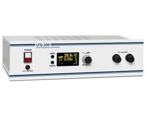
CABLE TRACING AND PINPOINTING FAULTS BY INDUCTION METHOD
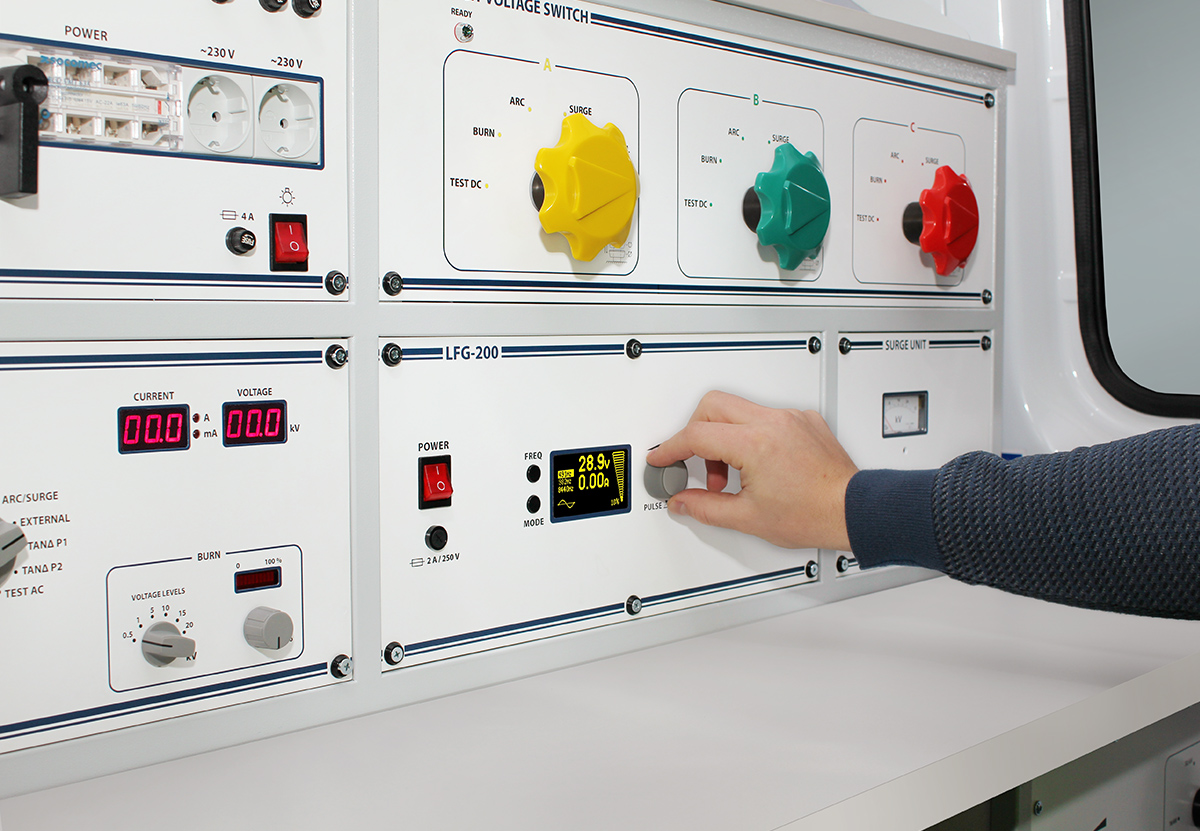
Cable test van ETL-35K can optionally be supplied with LFG-200 low frequency generator providing up to 200 VA of output signal power.
Addition of the generator, turns ETL-35K into a powerful system for underground utilities tracing, their burial depth determination and cable faults pinpointing by the induction method.

DIELECTRIC DISSIPATION FACTOR MEASUREMENT
ETL-35K system can be equipped with an optional Tan Delta module for accurate measurement of capacitance and the dielectric dissipation factor at up to 10 kV voltage of industrial frequency.
Tan Delta measurement using cable test vans is most often used to assess the transformer insulators on the electrical substations.
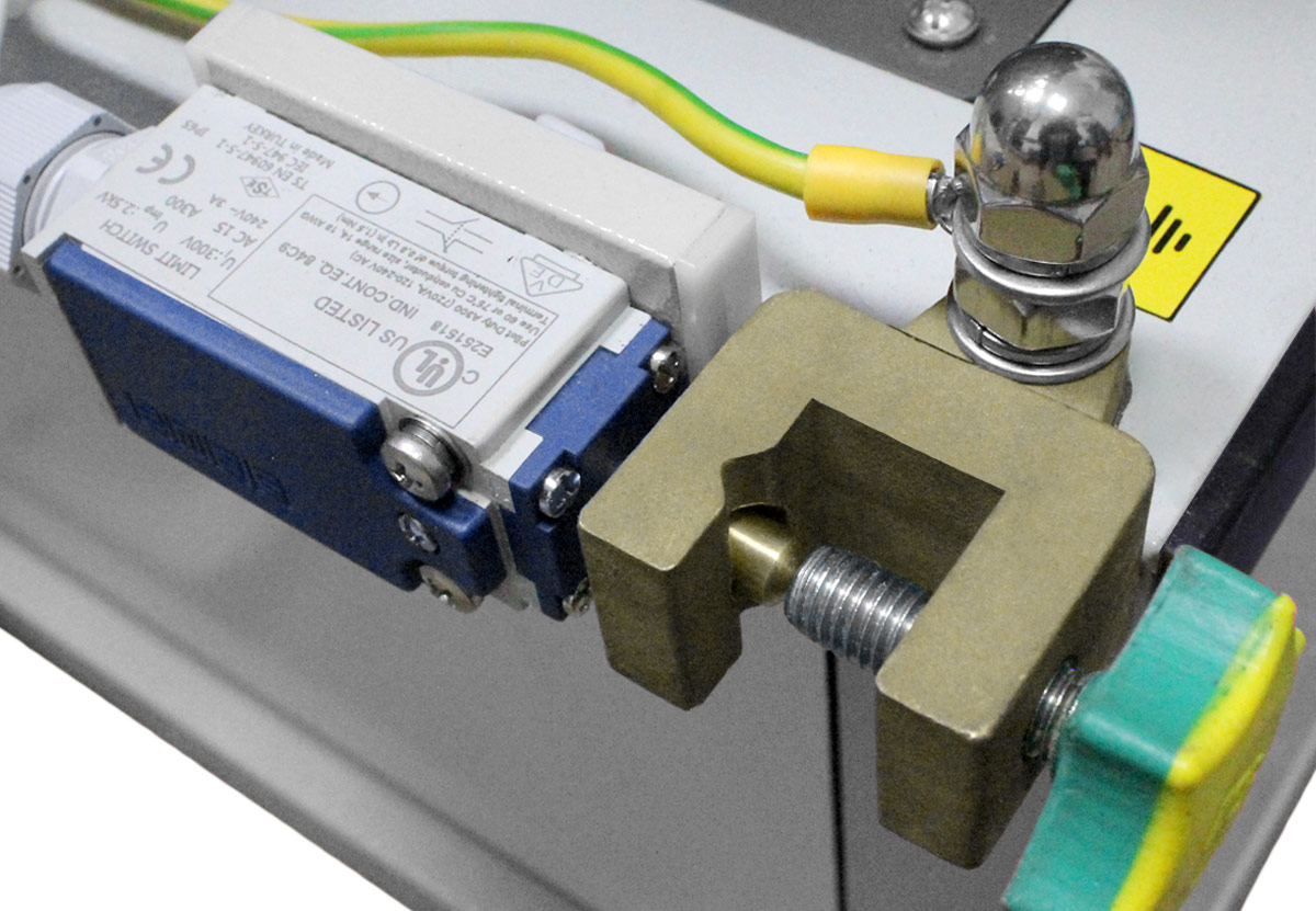
SAFETY
All cable test vans of ETL family are equipped with all-round operator safety systems consisting of the following modules and devices:
Grounding
- ✓ Protective earthing of the equipment and van chassis
- ✓ Operating grounding
- ✓ Vehicle chassis potential monitoring
- ✓ Continuous grounding monitoring system
- ✓ Automatic discharge device
Protection
- ✓ Overvoltage
- ✓ Overcurrent
- ✓ Overheating
- ✓ Position monitoring of high-voltage switches
High voltage switch off
- ✓ EMERGENCY STOP button
- ✓ Power keylock switch
- ✓ Open rear door monitoring


| Connection | Number of phases | 3 |
| DC testing | Output current indication range | 0 … 60 kV |
| Output current indication range |
■ 0.01 … 3 mA, resolution 0.01 mA ■ 0 … 30 (65)* mA, resolution 0.1 mA |
|
| Indication | Digital indication of output voltage and current in real time | |
| Relative voltage and current indication error | ± 3 % of full range | |
| AC testing | Output voltage adjustment and indication range | 0 … 100 kV |
| Output current indication range | 0 … 75 (175) mA | |
| Indication | Digital indication of output voltage and current in real time | |
| Relative voltage and current indication error | ± 3 % of full range | |
| Fault conditioning (burning) | Output DC voltage levels, adjustment and indication ranges |
Level 1: 0 … 0.5 kV Level 2: 0 … 1 kV Level 3: 0 … 5 kV Level 4: 0 … 10 kV Level 5: 0 … 20 kV |
| Output current (open-circuit run) |
■ up to 12 A in the 0 … 0.5 kV range ■ up to 6 A in all other ranges |
|
| Indication | Digital indication of output voltage and current in real time | |
| Relative voltage and current indication error | ± 3 % | |
| Fault pre-location | Pre-location methods |
■ TDR (impulse reflection method) ■ ARC / ARC multi-shot (single impulse / multiple impulse arc reflection method) ■ ICE (impulse current method) ■ DECAY (voltage decay method) |
| Fault detection ranges (for velocity factor 1.50 or v/2 = 100 m/μs) | 0 … 60 / 120 / 250 / 500 / 1000 / 2000 / 5000 / 10 000 / 20 000 / 50 000 / 120 000 m | |
| Fault detection resolution: | ||
| ■ for velocity factor 1.50 (v/2 = 100 m/μs) | 0.5 m | |
| ■ for velocity factor 1.87 (v/2 = 80.2 m/μs) | 0.4 m | |
| Distance to fault detection accuracy | 0.2 % of selected range | |
| Sampling rate | 200 MHz | |
| Time-domain accuracy | 0.01 % | |
| Output impedance adjustment range | 2 … 100 Ω, resolution 2 Ω | |
| Probe pulse parameters: | ||
| ■ voltage | 45 V | |
| ■ width adjustment range | 10 ns … 100 μs | |
| Gain adjustment range | minus 21 … + 69 dB | |
| Velocity factor adjustment range | 0.750 … 3.000, resolution 0.001 | |
| Propagation velocity (v/2) adjustment range | 50.0 … 200.0 m/μs, resolution 0.1 m/μs | |
| Internal memory of the reflectometer: | ||
| ■ historical measurements with associated settings | up to 1000 | |
| ■ reference cable propagation velocity (v/2) records | up to 500 | |
| Tracing and fault pinpointing with inductive method | Sets of operating frequencies |
491 / 982 / 8440 Hz 480 / 1450 / 9820 Hz 526 / 1024 / 8928 Hz 1024 / 2048 / 9820 Hz |
| Number of frequencies used simultaneously | 1 … 3 | |
| Modulation type | Amplitude | |
| Output power adjustment range | 0 … 200 V•A | |
| Operating mode |
■ Continuous ■ Pulse |
|
| Load resistance range within which the maximum output power may be achieved | 0.5 … 1000 Ω | |
| Load resistance matching | Automatic | |
| Fault pinpointing with acoustic method | Surge voltage levels and adjustment ranges |
Level 1: 0 … 8 kV Level 2: 0 … 16 kV Level 3: 0 … 32 kV |
| Surge energy at each level | up to 2000 J | |
| Surge rate |
■ Single pulse, manually triggered ■ 4 … 12 surges/min, automatic mode |
|
| Indication | Digital indication of output voltage in real time | |
| Dielectric dissipation factor (Tangent Delta) measurement | Measured values |
■ Electrical capacitance ■ Tan δ ■ Operating voltage ■ Operating frequency |
| Measurement modes |
■ Direct ■ Inverted |
|
| Measurement voltage | up to 10 kV | |
| Maximum load capacitance |
■ 64 nF @ 5 kV ■ 32 nF @ 10 kV |
|
| Measurement error: | ||
| ■ Electrical capacitance | ± 5*10-2 % | |
| ■ Tan δ | ± (0.01*tan δ + 1*10-4) | |
| ■ Operating voltage | ± 1.5 % | |
| ■ Operating frequency | ± 0.1 Hz | |
| Safety | Isolation transformer | 8 (18) kV•A |
| Grounding |
■ Protective earthing of the equipment and van chassis ■ Operating grounding ■ Vehicle chassis potential monitoring ■ Continuous grounding monitoring system ■ Automatic discharge device |
|
| Protection |
■ Overvoltage ■ Overcurrent ■ Overheating |
|
| High voltage presence signalling |
■ Light signalling (optional) ■ Acoustic signalling (optional) |
|
| High voltage switch off |
■ EMERGENCY STOP button ■ Power keylock switch ■ Open rear door monitoring |
|
| Power supply and consumption | Mains supply voltage | 230 VAC, ± 10 % |
| Mains supply frequency | 50 Hz | |
| Power consumption | up to 8.0 (19) kV•A |
* Parameters in parentheses apply to the systems with TIOG-100/17.5 transformer.