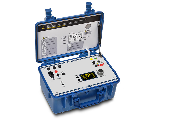
LFG-50
LOW FREQUENCY GENERATOR
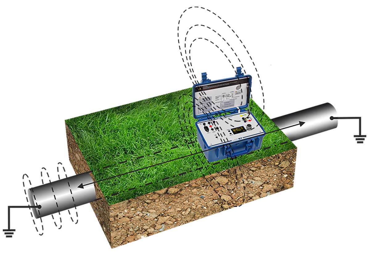
Generator LFG-50 is used in route tracing systems as a source of a low frequency electrical signal for the following applications:
- tracing – finding the route and determining the burial depth of underground cables and other hidden utilities;
- fault location – pinpointing inter-core and core-to-sheath short circuits faults;
- cable identification – identifying a correct cable from a bunch.
HIGH POWER


LFG-50 stands out from other portable low frequency generators with its unusually high output power (up to 50 VA). High power output significantly extends the useful signal range and ensures accurate location even under such adverse factors as large burial depth of an object, wet soil, external inductance, etc.
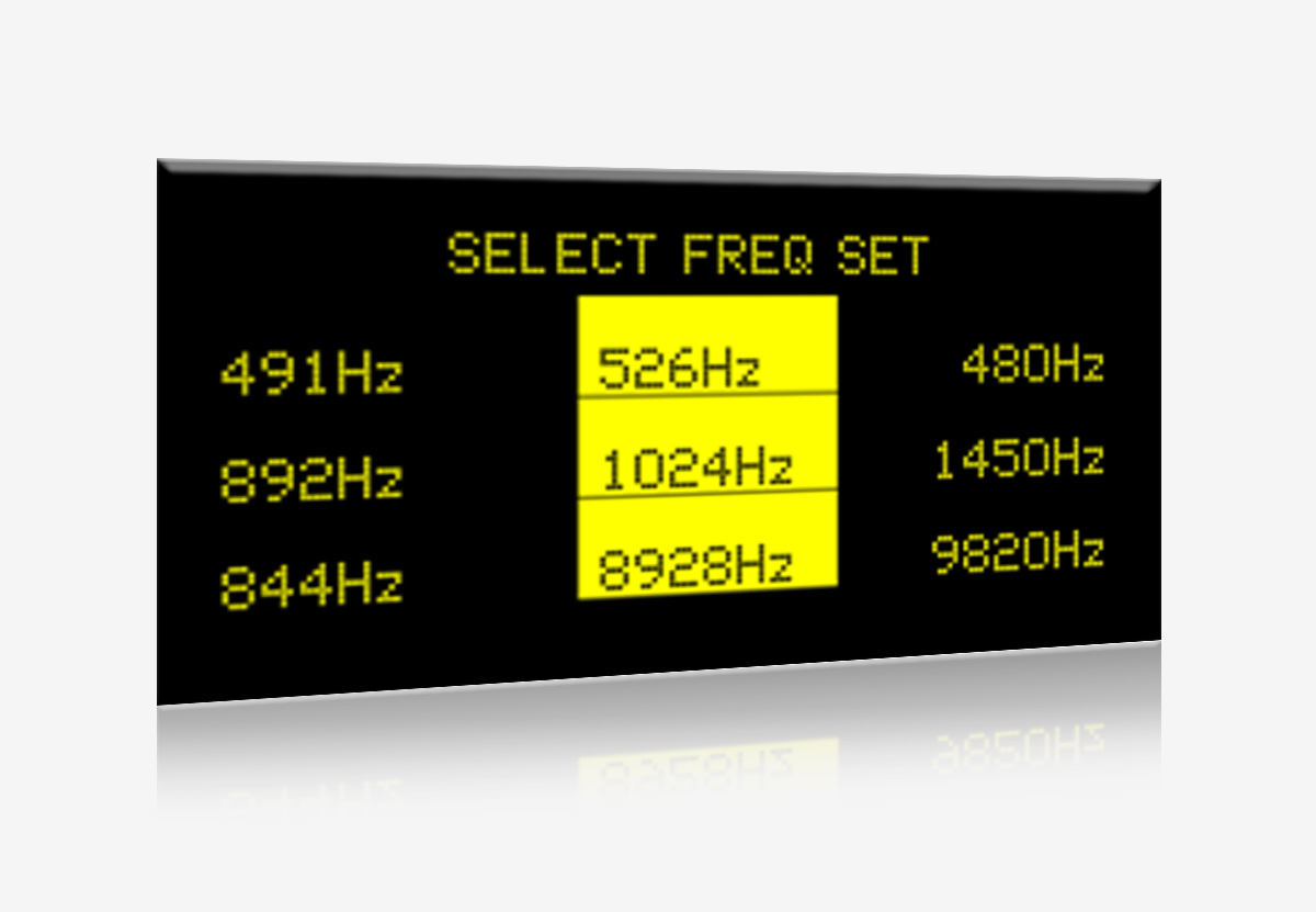
WIDE SELECTION OF OPERATING FREQUENCIES
The generator features four sets of frequencies each containing three different frequencies. Frequencies may be customized on request. The wide frequency selection allows for almost any low frequency signal receiver to be used in conjunction with the generator.
AUTOMATIC IMPEDANCE MATCHING
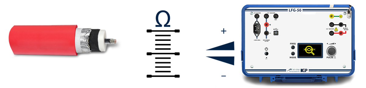
The output impedance of the generator is automatically matched to the load, which ensures maximum signal power in a wide resistance range (0.5 ... 1000 Ω). This function makes LFG-50 suitable for use in adverse location conditions as well as enables effective tracing of very long cables.

MULTI-FREQUENCY MODE
The generator can output complex signals formed by adding a number of different frequencies together.
Signals formed with adding two-frequencies allow a compatible signal receiver to determining a burial depth of an object during tracing.
Three-frequency signals allow to fine tune the receiver right during the tracing process.
PULSE MODE

Signals generation in pulse mode simplifies location at high levels of background noise.
Pulse mode can also significantly extend the operating time of the generator when powered from a built-in battery.
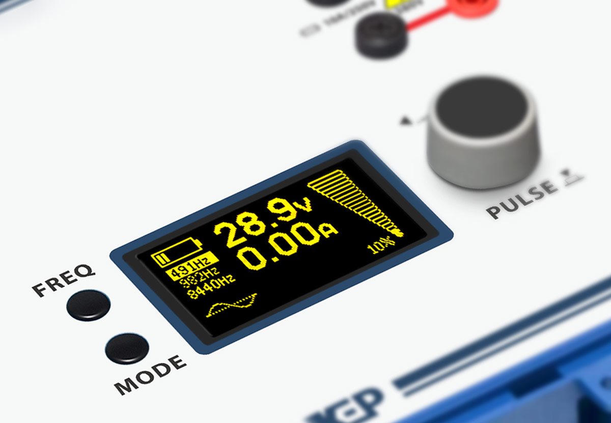
BRIGHT OLED DISPLAY
The generator is equipped with a monochrome OLED display which provide clear readings even in bright sunlight.
The display conveniently and clearly indicates the operating mode, output power, current and voltage levels, built-in battery charge and other operating parameters.
BUILT-IN TRANSMISSION ANTENNA
Along with a direct connection, it is possible to connect the generator to an object using inductive coupling (by means of a signal clamp or a built-in transmission antenna). Inductive coupling is used when either there is no access to the conductive parts of the object or it is energized.

PORTABILITY
Portable generator LFG-50 weighs only 8 kg and is enclosed in a compact and shock-resistant case protecting it against mechanical damage, dust and moisture. The generator is equipped with a built-in rechargeable frost-resistant lithium-iron-phosphate (LiFePO4) battery and an integrated control panel LED illumination. The ability to power the generator from the battery, mains or an external 12-volt DC source makes LFG-50 well suited for field operation.


| System parameters | Sets of operating frequencies* |
491 / 982 / 8440 Hz 480 / 1450 / 9820 Hz 526 / 1024 / 8928 Hz 1024 / 2048 / 9820 Hz |
| Number of frequencies used simultaneously | 1 … 3 | |
| Frequency selection | Manual | |
| Modulation type | Amplitude | |
| Output power adjustment range | 0 … 50 V•A, resolution 2,5 V•A | |
| Operating modes |
■ Continuous ■ Pulse |
|
| Modulation (pulse) frequency | 1 Hz | |
| Load resistance range within which the maximum output power may be achieved | 0.5 … 1000 Ω | |
| Load resistance matching | Automatic | |
| Maximum output open-circuit voltage | 235 VRMS | |
| Ranges and accuracies of indicated parameters | Output voltage | 0.1 … 240 VRMS |
| Output current | 0.01 … 9.99 ARMS | |
| Phase shift angle | 0 … 90° | |
| Relative error of output voltage indication | 5 % | |
| Relative error of output current indication | 5 % | |
| Interfaces | Display | Monochrome OLED |
| Connection interfaces | USB-B (service only) | |
| Control panel illumination | LED light in the lid | |
| Safety | Grounding | ■ Protective earthing |
| Protection |
■ Overload ■ Overheating ■ Galvanic isolation of the output signal circuit |
|
| Fuses |
■ Mains power circuit: 1A, 250 V ■ Battery power circuit: 10 A, 250 V ■ External power circuit: 10 A, 250 V ■ Output signal circuit: 10 A, 250 V |
|
| Ingress protection rating (according to EN 60529) | IP 54 (with lid closed) | |
| Power supply and consumption | Internal rechargeable battery | 12 V, 10 A•h, LiFePO4 |
| Battery life ** | over 1 h @ maximum output power | |
| Average battery charge time | 3 h | |
| External power source voltage | 10 … 15 VDC | |
| Current consumption when powered from external power source (@ 12 VDC) | up to 8 A | |
| Mains supply voltage | 230 VAC, ± 10 % | |
| Mains supply frequency | 50 / 60 Hz | |
| Power consumption when powered from mains supply | up to 100 V•A | |
| Physical | Dimensions, H × W × D | 266 × 366 × 270 mm |
| Weight | 8 kg |
* Sets of operating frequencies may be changed on the customer's request in the range of 100 … 10000 Hz.
** Battery life depends on selected power output and many other factors; actual results may vary. Battery recharge cycle count is limited.