LFG-200
LOW FREQUENCY GENERATOR
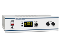
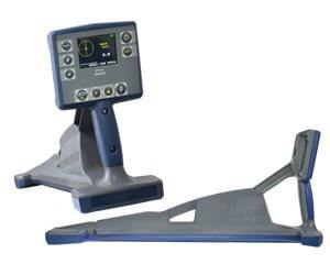
LFG-200 is a cable test van-mountable low frequency signal generator used as part of a cable tracing and fault location set for the following applications:
- tracing – determining the route and burial depth of underground cables and other hidden utilities;
- fault location – inter-core and core-to-sheath short circuits faults pinpointing;
- cable identification – identifying a correct cable in a bunch.
UNCOMPROMISED POWER


Compared to other generators of its class, LFG-200 is characterized by increased output power (up to 200 VA) enabling a significantly larger location range in comparison with analogues. This advantage makes it possible to accurately pinpoint faults in the utilities buried deeply in wet soil and ensures consistent tracing results even at strong inductive interference levels.

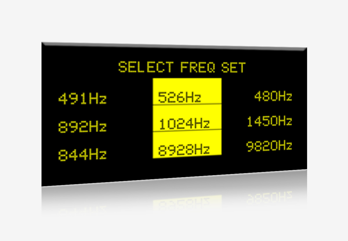
WIDE SELECTION OF OPERATING FREQUENCIES


Output signal frequency may be selected from a set of 12, which can be either default or by customised at customer’s request. A large set of frequencies allows to use the generator with almost any locator operating in the low frequency range.
AUTOMATIC IMPEDANCE MATCHING


The automatic impedance matching provides the maximum signal power in a wide load resistance range (0.5 ... 1000 Ω). This feature significantly improves the quality of location when tracing longer lines and/or operating in difficult conditions.

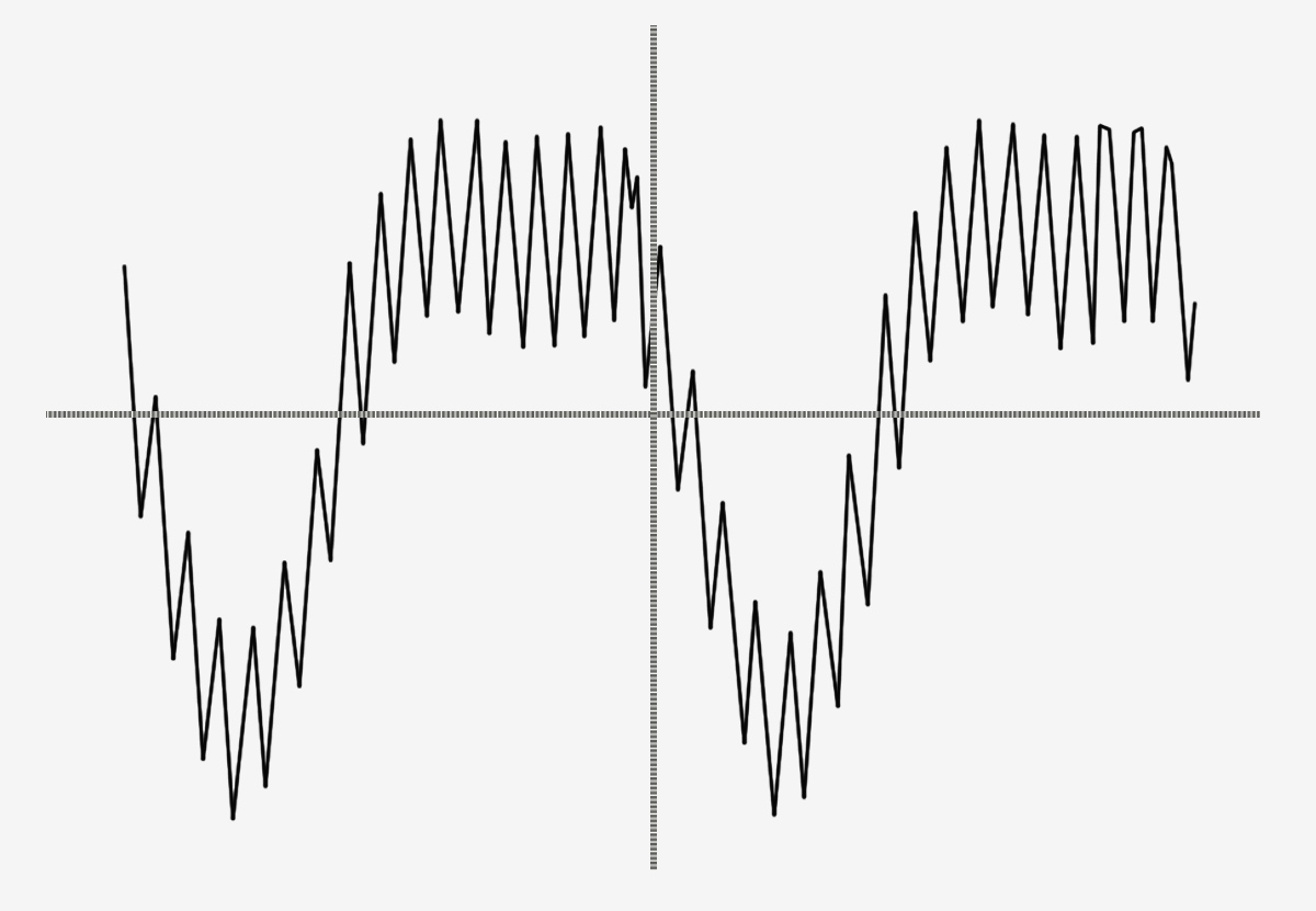
MULTI-FREQUENCY MODE


A complex output signal can be formed by adding two or three operating frequencies together.
Two-frequency signal is used for tracing utilities with a possibility to determine their burial depth.
When three-frequency signals are generated, it is also possible to fine-tune the receiver during tracing.
PULSE MODE


Operating LFG-200 in the pulse mode provides an easier signal detection at high level of extraneous noise.

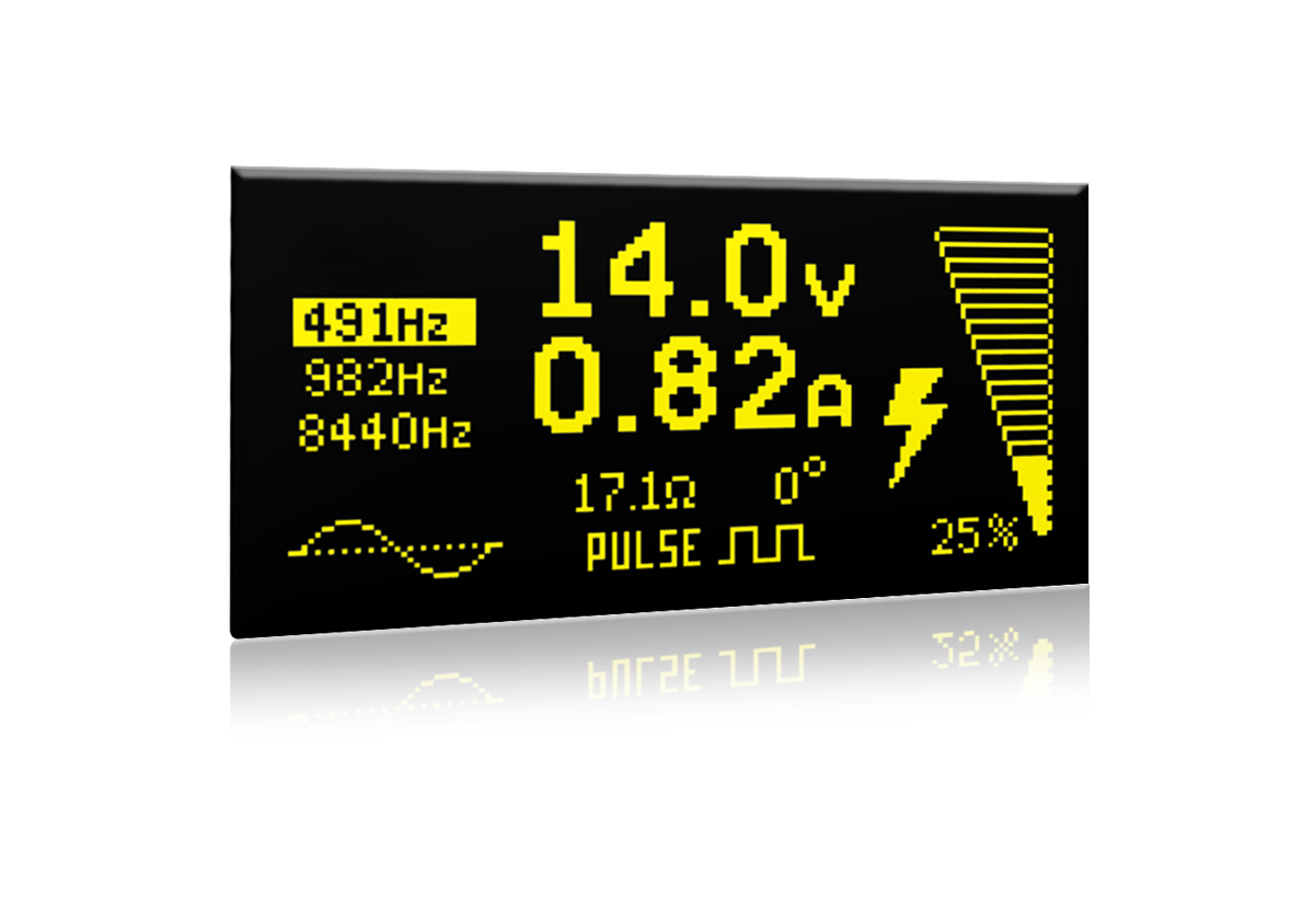
INFORMATIVE OLED DISPLAY


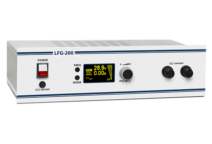
The generator is fitted with a monochrome OLED display featuring convenient graphical indication of the operating mode, signal power, current, voltage, and other operating parameters.
INTEGRATION WITH CABLE TEST VANS

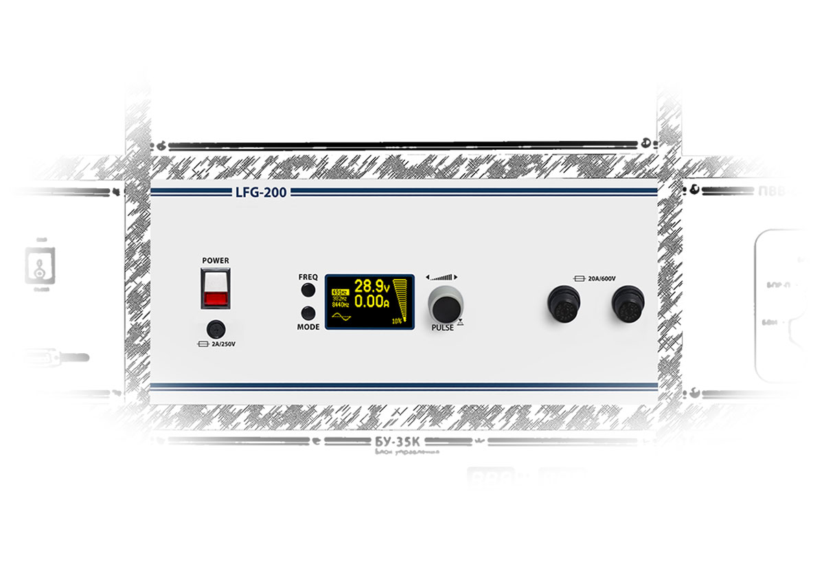
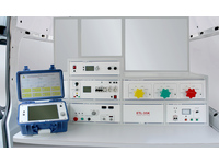
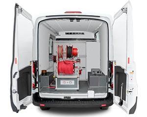
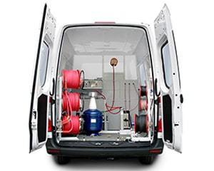
The unified casing size allows for easy installation of the generator LFG-200 in the rack of a cable test van (ETL-series).

| System parameters | Sets of operating frequencies* |
491 / 982 / 8440 Hz 480 / 1450 / 9820 Hz 526 / 1024 / 8928 Hz 1024 / 2048 / 9820 Hz |
| Number of frequencies used simultaneously | 1 … 3 | |
| Frequency selection | Manual | |
| Modulation type | Amplitude | |
| Output power adjustment range | 0 … 200 V•A, resolution 10 V•A | |
| Operating modes |
■ Continuous ■ Pulse |
|
| Modulation (pulse) frequency | 1 Hz | |
| Load resistance range within which the maximum output power may be achieved | 0.5 … 1000 Ω | |
| Load resistance matching | Automatic | |
| Maximum output open-circuit voltage | 460 VRMS | |
| Ranges and accuracies of indicated parameters | Output voltage | 0.1 … 450 VRMS |
| Output current | 0.01 … 20 ARMS | |
| Phase shift angle | 0 … 90° | |
| Relative error of output voltage indication | 5 % | |
| Relative error of output current indication | 5 % | |
| Interfaces | Display | Monochrome OLED |
| Connection interface | USB-B (service only) | |
| Safety | Grounding | ■ Protective earthing |
| Protection |
■ Overload ■ Overheating ■ Galvanic isolation of the output signal circuit |
|
| Fuses |
■ Mains power circuit: 2A, 250 V ■ Output signal circuit: 20 A, 600 V |
|
| Power supply and consumption | Mains supply voltage | 230 VAC, ± 10 % |
| Mains supply frequency | 50 / 60 Hz | |
| Power consumption when powered from mains supply | up to 400 V•A | |
| Physical | Dimensions, H × W × D | 133 × 482 × 350 mm |
| Weight | 8.3 kg |
* Sets of operating frequencies may be changed on the customer's request in the range of 100 … 10000 Hz.
