SWG-12 (SWG-32)
MOBILE CABLE TEST AND FAULT LOCATION SYSTEM
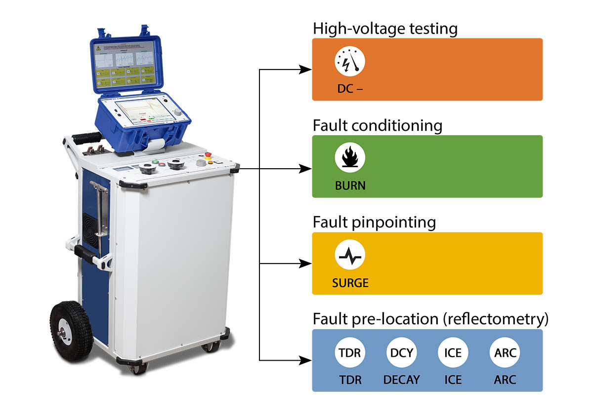
Mobile systems SWG-12 and SWG-32 are designed for the following applications:
- testing insulation of power cables with DC voltage up to 32 kV;
- conditioning faults by burning faulty cable insulation with DC current up to 100 mA at up to 32 kV voltage;
- pre-locating cable faults with an aid of the reflectometer RIF-9 using a low-voltage pulse reflection method (TDR) and high-voltage methods: voltage wave oscillation (DECAY), impulse current envelope (ICE), and arc reflection (ARC / ARC multi‑shot);
- pinpointing cable faults with an acoustic method with up to 2000 J surge wave generator and a suitable signal receiver.
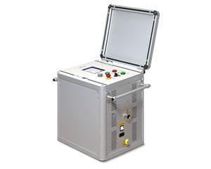
CABLE FAULT LOCATION MADE COMPACT

Under a single compact system SWG embodies all the main components of a fully-featured cable test van: a digital pulse reflectometer, a high-voltage step-up test transformer, a powerful surge wave generator and a burn unit.
Rich functionality along with small dimensions and durable design allows using SWG for most cable fault location tasks where a cable test van would traditionally have been utilised. In addition, the system can be used for withstand testing solid insulation with DC voltage up to 32 kV (for SWG-12 – 12 kV).
SWG-series systems can therefore be considered as an uncompromising solution for high-quality cable maintenance – these compact and mobile units provide the full range of functionality and feature safety functions commonly available only on fully-featured van-mounted cable test and fault location systems.
HIGH SURGE ENERGY
For pinpointing cable faults with the acoustic method, SWG comes equipped with a surge wave generator with the surge energy up to 2000 J (for SWG-12 – 1100 J).
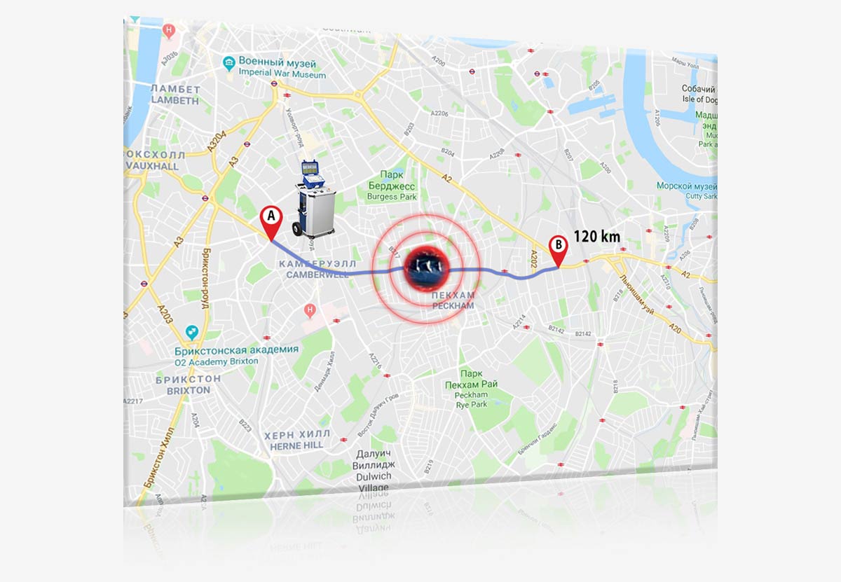
High surge energy contributes to a successful fault pinpointing by providing a powerful signal in the conditions of high background noise, deep cable burial, or distant fault location.
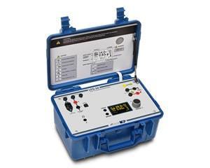
DETACHABLE REFLECTOMETER
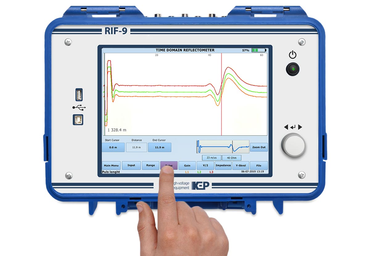
SWG systems are supplied with the digital pulse reflectometer RIF-9 which is used for pre-locating faults with the following methods:
Low-voltage method (stand-alone mode)
- TDR (time-domain reflectometry): low-resistance faults and breaks.
High-voltage methods (RIF-9 + high voltage source)
- ARC/ARC multi-shot (single impulse / multiple impulse arc reflection method): high-resistance and unstable faults.
- ICE (impulse current envelope method): high-resistance faults that cannot be converted to low-resistance ones by burning faulty insulation.
- DECAY (voltage wave oscillation method): faults with high breakdown voltage.
Detachable design makes it possible to pre-locate cable faults with the TDR method using the reflectometer separately from the SWG system.
BUILT-IN BURN UNIT
All SWG systems include a built-in burn unit with continuous output voltage adjustment.
Burn unit is used for fault conditioning by permanently destroying cable insulation in the point of a fault, making it possible to subsequently use fault pre-location methods.
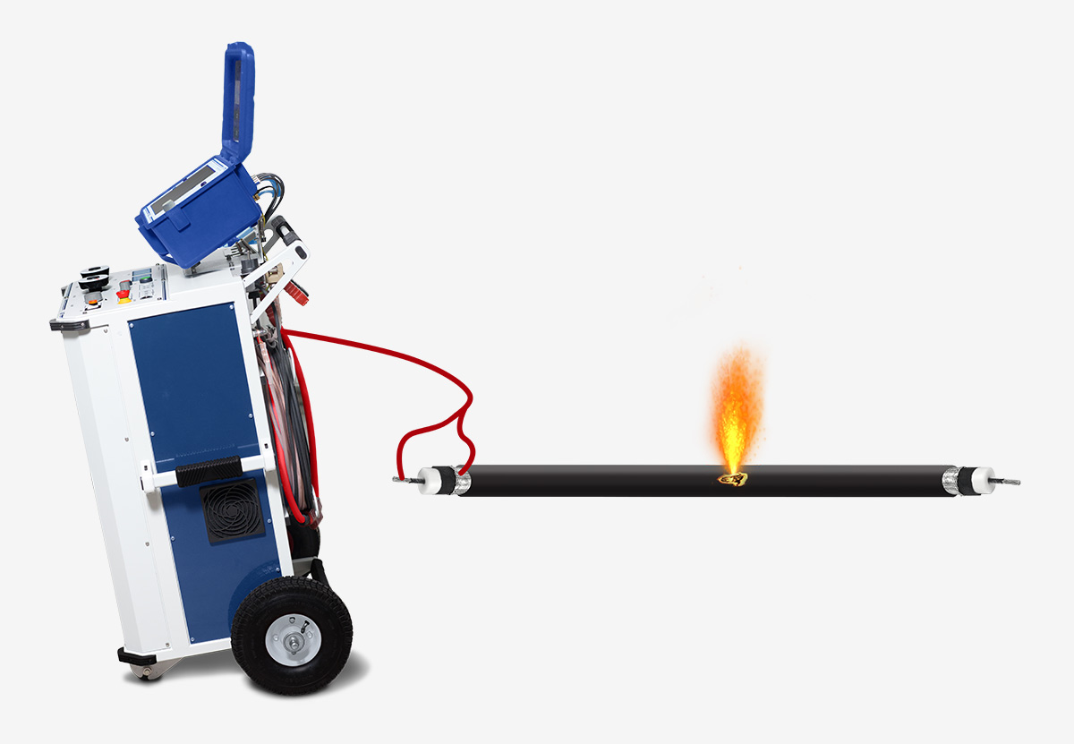
SURGE WAVE GENERATOR WITH A VOLTAGE LEVELS SWITCH
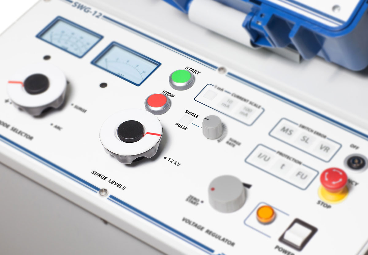
For an accurate cable fault pinpointing, SWG systems are equipped with a powerful surge wave generator.
The range of the generator output voltage adjustment is set using a tri-position voltage levels switch: 0 … 8 / 16 / 32 kV (for SWG-12 – 0 … 3 / 6 / 12 kV), which ensures a maximum surge energy in the entire operating range.
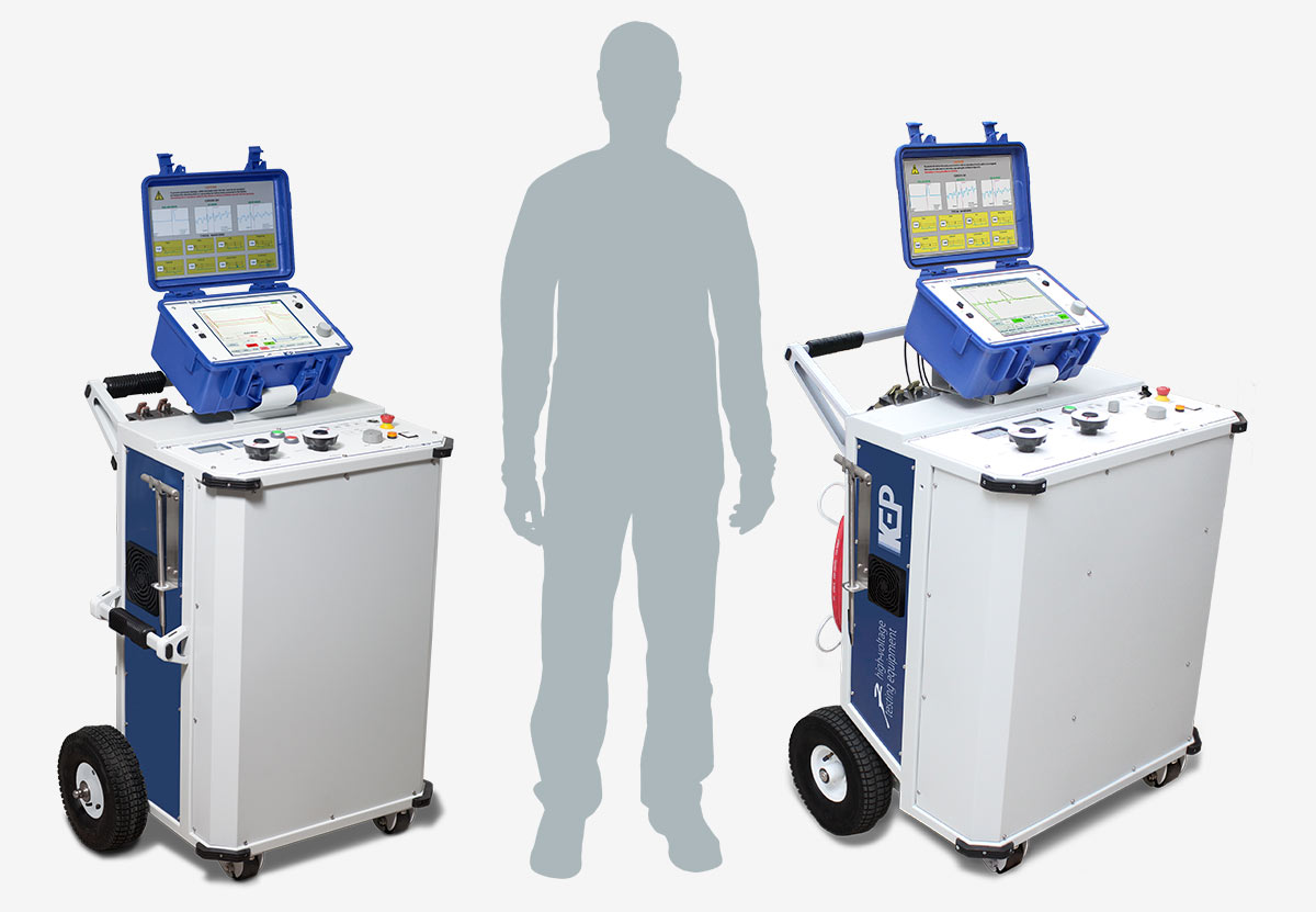
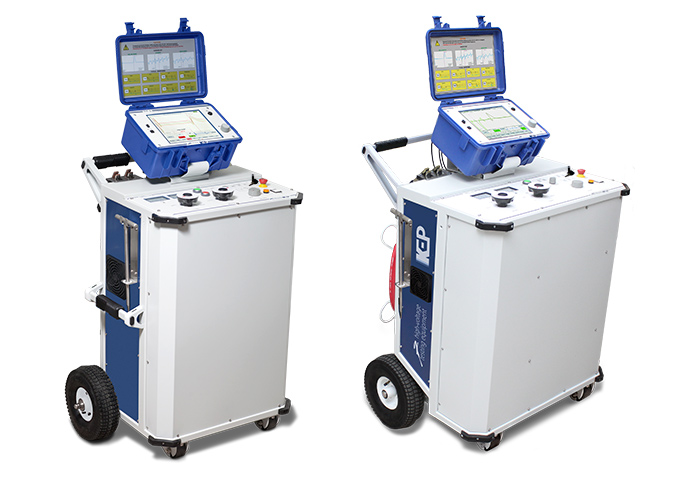
MOBILITY
The system is built in the form of a trolley with a detachable reflectometer affixed on the top.
All the power supply, earthing and high-voltage cables are conveniently stowed on the holders on the rear panel.
Ergonomic arrangement of controls, informative display of the reflectometer, and large trolley wheels provide operating convenience in the field conditions.
SAFETY
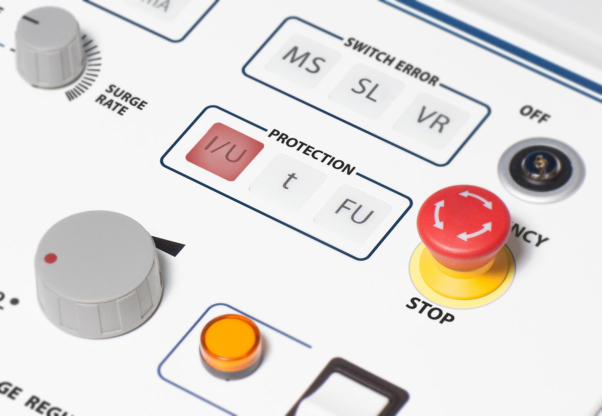
Operator safety is assured by both modern and traditional protective means provided by the SWG system.
Grounding
- ✓ Protective earthing
- ✓ Operating grounding
- ✓ Continuous grounding monitoring system
- ✓ Automatic discharge device
Protection
- ✓ Overvoltage
- ✓ Overcurrent
- ✓ Overheating
High voltage switch off
- ✓ EMERGENCY STOP button
- ✓ Power keylock switch
")
")
")
")
")
")
| SWG-12 | SWG-32 | ||
| DC testing | Output voltage adjustment and indication range | 0 … 12 kV | 0 … 32 kV |
| Output current indication range | 0 … 10 mA | ||
| Indication | Analogue indication of output voltage and current in real time | ||
| Relative voltage and current indication error | ± 3 % of full range | ||
| Fault conditioning (burning) | Output DC voltage levels, adjustment and indication range | 0 … 12 kV | 0 … 32 kV |
| Output current (open-circuit run) | up to 100 mA | ||
| Voltage adjustment type | Continuous | ||
| Indication | Analogue indication of output voltage and current in real time | ||
| Relative voltage and current indication error | ± 3 % of full range | ||
| Fault pre-location | Pre-location methods |
■ TDR (impulse reflection method) ■ ARC / ARC multi-shot (single impulse / multiple impulse arc reflection method) ■ ICE (impulse current method) ■ DECAY (voltage decay method) |
|
| Fault detection ranges (for velocity factor 1.50 or v/2 = 100 m/μs) | 0 … 60 / 120 / 250 / 500 / 1000 / 2000 / 5000 / 10 000 / 20 000 / 50 000 / 120 000 m | ||
| Fault detection resolution: | |||
| ■ for velocity factor 1.50 (v/2 = 100 m/μs) | 0.5 m | ||
| ■ for velocity factor 1.87 (v/2 = 80.2 m/μs) | 0.4 m | ||
| Distance to fault detection accuracy | 0.2 % of selected range | ||
| Sampling rate | 200 MHz | ||
| Time-domain accuracy | 0.01 % | ||
| Output impedance adjustment range | 2 … 100 Ω, resolution 2 Ω | ||
| Probe pulse parameters: | |||
| ■ voltage | 45 V | ||
| ■ width adjustment range | 10 ns … 100 μs | ||
| Gain adjustment range | minus 21 … + 69 dB | ||
| Velocity factor adjustment range | 0.750 … 3.000, resolution 0.001 | ||
| Propagation velocity (v/2) adjustment range | 50.0 … 200.0 m/μs, resolution 0.1 m/μs | ||
| Internal memory of the reflectometer: | |||
| ■ historical measurements with associated settings | up to 1000 | ||
| ■ reference cable propagation velocity (v/2) records | up to 500 | ||
| Fault pinpointing with acoustic method | Surge voltage levels and adjustment ranges | Level 1: 0 … 3 kV | Level 1: 0 … 8 kV |
| Level 2: 0 … 6 kV | Level 2: 0 … 16 kV | ||
| Level 3: 0 … 12 kV | Level 3: 0 … 32 kV | ||
| Surge energy at each level | up to 1100 J | up to 2000 J | |
| Surge rate |
■ Single pulse, manually triggered ■ 4 … 12 surges/min, automatic mode |
||
| Indication | Digital indication of output voltage in real time | ||
| Controls and interfaces | Connection interfaces |
■ USB-A (user memory stick, FAT32) ■ USB-B (PC connection) ■ RS-485 (service only) |
|
| Display (reflectometer RIF-9) | 10.4” colour TFT, 800 × 600 px, resistive touch | ||
| Operating modes switch | Manual | ||
| Surge voltage levels switch | Manual | ||
| Secondary control interface | Rotary encoder with “ENTER” button | ||
| Connections | HV test cable |
6 m (KEP-12) |
10 m (KEP-40) |
| Power supply cable | 10 m | ||
| Protective earthing cable (KEP-10GCt) | 10 m | ||
| Earthing control cable | 6 m | 10 m | |
| Safety | Grounding |
■ Protective earthing ■ Operating grounding ■ Continuous grounding monitoring system ■ Automatic discharge device |
|
| Protection |
■ Overvoltage ■ Overcurrent ■ Overheating |
||
| High voltage switch off |
■ EMERGENCY STOP button ■ Power keylock switch |
||
| Ingress protection rating (according to EN 60529) | IP 30 | ||
| Power supply and consumption | Mains supply voltage | 230 VAC, ± 10 % | |
| Mains supply frequency | 50 Hz (60 Hz option) | ||
| Power consumption | up to 1.0 kV•А | up to 2.0 kV•А | |
| Physical | Dimensions, H × W × D (with RIF-9 installed) | 1172 × 775 × 603 mm | 1215 × 764 × 675 mm |
| Total weight (with RIF-9 and connection cables) | 120 kg | 185 kg | |