UPA
CIRCUIT BREAKER TEST SYSTEMS
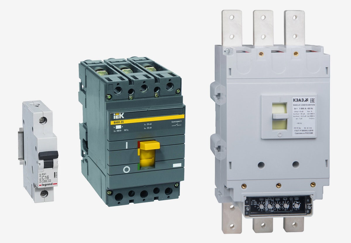
Mobile UPA-series systems are designed for testing tripping characteristics of the magnetic and thermal-magnetic circuit breakers used in the AC circuits of industrial frequency.
The maximum test current delivered by UPA systems is:
- UPA-1 — 1 kA
- UPA-3 — 3 kA
- UPA-6 — 6 kA
- UPA-10 — 10 kA
- UPA-16 — 16 kA
- UPA-20 — 20 kA

RELIABLE TRIP CURVES CONTROL


UPA-series systems may be used (with an aid of an external voltage regulator) for testing time-current characteristics of the circuit breakers according to IEC 60898-1:2019 or IEC 60934:2019.
VERSATILITY
UPA systems can be used for a quick preliminary checking of the tripping functionality, a full time-current characteristics testing, as well as checking the influence of a single-pole load on the tripping of a multi-pole circuit breaker.
TIME-LIMITED CURRENT GENERATION
UPA systems can operate in a continuous or time-limited current generation cycles. Fast switch off time allows to select the exact test duration as short as 50 ms.
VERSATILE CURRENT SOURCE
The current source contains a lightweight, compact and highly efficient toroidal transformer.
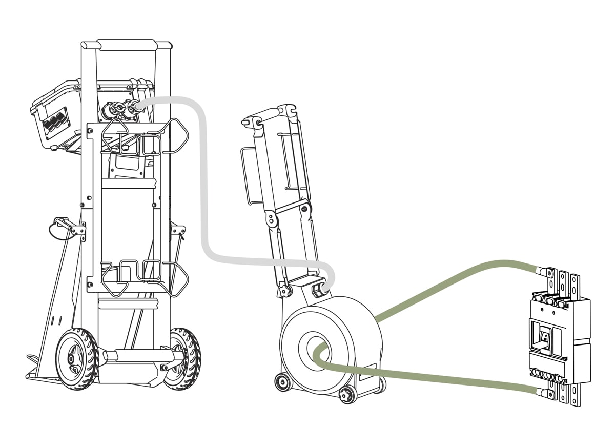
The system connects to a circuit breaker under the test via flexible current conductors which are passed through the toroidal transformer, forming its secondary winding. The strength of the output current is regulated by the quantity and the number of turns flexible current conductors make abound the transformer. This solution allows to obtain a wide range of output currents using just one current source.
SAFE DESIGN
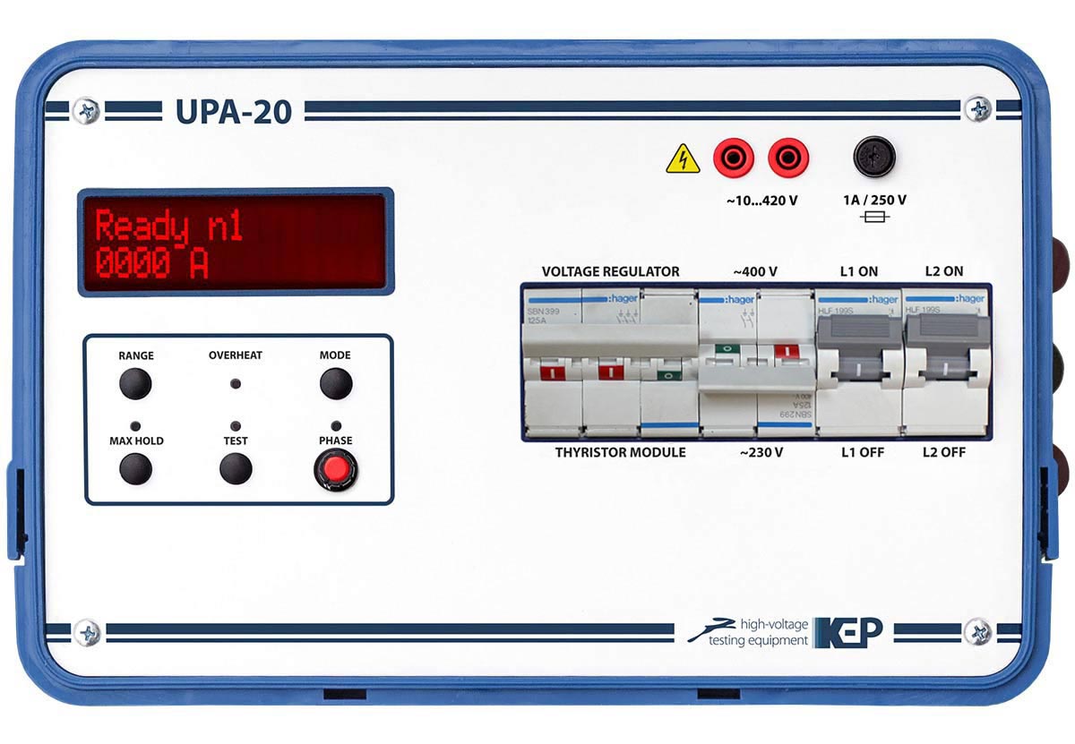
All UPA systems comprise of two main modules - a control unit and a current source, complete with the necessary set of connection cables.
Two-unit design allows an operator to remain at a safe distance away from the high current source and the circuit breaker under test.

MOBILITY
All modules of the UPA-series systems are individually portable, but are supplied as standard they on a trolley for easy transportation.
The narrow wheelbase of the trolley makes it ideal for delivering and deploying the system in the often small distribution rooms.
")

")

")


| UPA-1 | UPA-3 | UPA-6 | UPA-10 | UPA-16 | UPA-20 | |||
| Output current | Maximum value | 1 kA | 3 kA | 5 kA | 10 kA | 16 kA | 20 kA | |
| Current measurement ranges in amperes | one turn | 10 … 100 А | 100 … 1000 А | 200 … 4000 А | ||||
| two turns | 5 … 50 А | 50 … 500 А | 100 … 2000 А | |||||
| three turns | 3.3 … 33 А | 33 … 330 А | 66.7 … 1333 А | |||||
| four turns | 2.5 … 25 А | 25 … 250 А | 50 … 1000 А | |||||
| five terns | 2 … 20 А | 20 … 200 А | 40 … 800 А | |||||
| Current measurement ranges in kiloamperes | one turn | 0.1 … 1 kA | 1 … 3 kA | 1 … 6 kA | 1 … 10 kA | 3 … 16 kA | 3 … 20 kA | |
| two turns | 0.05 … 0.5 kA | 0.5 … 1.5 kA | 0.5 … 3 kA | 0.5 … 5 kA | 1.5 … 8 kA | 1.5 … 10 kA | ||
| three turns | 0.03 … 0.33 kA | 0.33 … 1 kA | 0.33 … 2 kA | 0.33 … 3.3 kA | 1 … 5.33 kA | 1 … 6.67 kA | ||
| four turns | 0.025 … 0.25 kА | 0.25 … 0.75 kA | 0.25 … 1.5 kA | 0.25 … 2.5 kA | 0.75 … 4 kA | 0.75 … 5 kA | ||
| five turns | 0.02 … 0.2 kA | 0.2 … 0.6 kA | 0.2 … 1.2 kA | 0.2 … 2 kA | 0.6 … 3.2 kA | 0.6 … 4 kA | ||
| Measurement error * | ± 3 % of maximum value in a given range | |||||||
| System parameters | Current generation cycles |
■ Continuous (up to 7200 s) ■ Time-limited (50 / 100 / 200 / 400 / 600 / 800 / 990 ms, 10 s) ** |
||||||
| Ranges of test duration measurement * |
■ 50 … 990 ms ■ 1 … 7200 s |
|||||||
| Absolute test duration measurement error in 50 … 990 ms range * | ± 20 ms | |||||||
| Relative test duration measurement error in 1 … 7200 s range * | ± 3 % | |||||||
| Open-circuit voltage (with one current conductor turn and 220 V voltage supply to the current source) | 0.9 V | 1.2 V | 0.9 V | |||||
| Maximum load cycle at maximum output current *** | 10 s | |||||||
| Power adjustment | Range of adjustment of the voltage supply to the current source when powered from 230 V mains | 5 … 250 V | ||||||
| Range of adjustment of the voltage supply to the current source when powered from 400 V mains | - | 230 … 450 V | ||||||
| Interfaces | Display | Monochrome, 2 lines, 20 characters each | ||||||
| Safety | Grounding | ■ Protective earthing | ||||||
| Protection |
■ Overcurrent ■ Overheating |
|||||||
| Power supply and consumption | Mains supply voltage | 230 VAC, ± 10% | ||||||
| Mains supply frequency | 50 Hz (60 Hz option) | |||||||
| Power consumption | up to 3.6 kV•А | up to 7.5 kV•А | up to 20 kV•А | up to 37 kV•А | up to 50 kV•А | |||
| Physical | Control unit dimensions H × W × D | 180 × 366 × 270 mm | 180 × 374 × 270 mm | |||||
| Current source dimensions with (without) handle, H × W × D | 223 × 110 × 253 mm (340 × 215 × 253 mm) |
(378 × 340 × 366 mm) | (378 × 340 × 375 mm) | |||||
| Overall system dimensions (when mounted on the handling trolley), H × W × D | 1117 × 451 × 500 mm | 1117 × 470 × 495 mm | ||||||
| Control unit weight | 4.9 kg | 5.5 kg | 6.4 kg | |||||
| Current source weight with (without) handle | 17 kg (19 kg) | (40 kg) | (60 kg) | |||||
| Total system weight (including handling trolley and accessories) | 41 kg | 80 kg | 108 kg | |||||
* The specified metrological characteristics are only valid when the system is used with an external voltage regulator.
** Pre-set time limits for current generation may be changed on request.
*** If the output current exceeds 1000 A, the test duration should not exceed 10 s.

